AVR Digital I/O
3. Pin Names and Locations
Digital I/O pins on the AVR microcontroller are grouped into ports. Each port has up to eight pins assigned to it. However, each pin can be individually configured. So, you can have a mix of input and output pins on the same port.
Ports are designated by a letter and pins are numbered starting at 0. For example, the first pin on port B is named PB0 and the third pin on port D is named PD2. Figure 1 shows the names and locations of the pins on the ATmega328P for the PDIP package, as well as the corresponding locations on the Arduino Uno board.
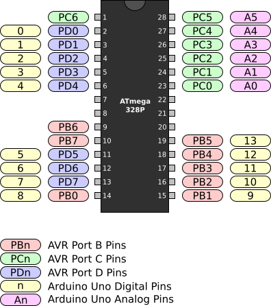
Figure 1. ATmega328P PDIP Pin Names and Locations
For those coming from an Arduino background, there are a couple things to take note. Firstly, you may notice that not all the digital I/O pins are available for use on the Arduino Uno board. This is because these pins are being used for alternate functions. PC6 is being used for device reset and PB6 and PB7 are connected to the crystal on the board. Secondly, even though the analog pins A0 - A5 can be used with the Analog-to-Digital converter, they may also be used for digital I/O.
Now that we know the names of the pins and where they are located, we can start using them.