AVR Digital I/O
5. Inputs
Using digital I/O pins as inputs gives us the ability to do things like read the state of a pushbutton or hall effect sensor. Just like outputs, configuring and using pins as inputs is easy to do.
There are two main steps for using digital inputs:
- Set the direction of the pin to input
- Read the value of the pin
To set the direction of the pin to be an input you will use the Data Direction Register. Each port has a data direction register that is used to set the direction of each of its pins. A value of 0 in the data direction register indicates that the pin is an input. At reset all bits in the data direction register are set to 0. The following example shows setting pin PD2 to be an input. Read the Wikipedia page on bit manipulation to get a refresher on clearing bits in C.
1
2
// Configure PD2 as an input using the Data Direction Register D (DDRD)
DDRD &= ~(1 << DDD2)
To clean things up a bit we can use the _BV macro which converts a bit number into a byte value.
1
2
// Configure PD2 as an input using the Data Direction Register D (DDRD)
DDRD &= ~_BV(DDD2);
To read the value of a pin you will use the Port Pin Input Register. Each port has a pin input register that is used to read the value of each of its pins. A value of 1 in the port pin input register indicates a high value on the pin. A value of 0 in the port pin input register indicates a low value on the pin. The following example shows reading the PD2 pin.
1
2
// Read PD2 using the Port D Pin Input Register (PIND)
uint8_t pin_value = PIND & _BV(PIND2);
In general, its a bad idea to leave input pins floating. Instead, pull-up or pull-down resistors should be used so that pins are always in a well defined logic state. The good news is that the AVR has builtin pull-up resistors that you can use, reducing the number of external components. To enable the pull-up resistor on a pin, you will use the Data Register. A value of 1 in the port data register enables the pull-up resistor on the pin. A value of 0 in the port data register disables the pull-up resistor on the pin. The following example show enabling the pull-up resistor on the PD2 pin.
1
2
// Enable the pull-up resistor on PD2 using the Port D Data Register (PORTD)
PORTD |= _BV(PORTD2);
A full working example of applying what we have covered so far is listed below. This example configures PD2 as an input with a pull-up resistor and then repeatedly checks the pin. If the pin is high, PB5 outputs a low value, which will turn the LED off. If the pin is low, PB5 outputs a high value, which will turn the LED on.
1
2
3
4
5
6
7
8
9
10
11
12
13
14
15
16
17
18
19
20
21
22
23
24
25
26
27
28
29
30
31
32
33
#include <avr/io.h>
int main(void)
{
// Configure PD2 as an input using the Data Direction Register D (DDRD)
DDRD &= ~_BV(DDD2);
// Enable the pull-up resistor on PD2 using the Port D Data Register (PORTD)
PORTD |= _BV(PORTD2);
// Configure PB5 as an output using the Port B Data Direction Register (DDRB)
DDRB |= _BV(DDB5);
// Loop forever
while (1)
{
// Read PD2 using the Port D Pin Input Register (PIND)
if (PIND & _BV(PIND2))
{
// PD2 is high, so button is released
// Set PB5 low using the Port B Data Register (PORTB)
PORTB &= ~_BV(PORTB5);
}
else
{
// PD2 is low, so button is pressed
// Set PB5 high using the Port B Data Register (PORTB)
PORTB |= _BV(PORTB5);
}
}
}
The circuit for this example should be wired according to Figure 1. If you run this example on an Arduino Uno, you will see the LED that is connected to Arduino pin 13 turning ON when the push button is pressed and turning OFF when the push button is released.
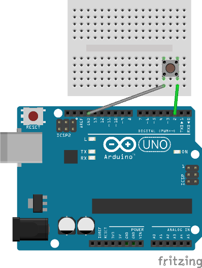
Figure 1. Input example wiring
Make sure to orient the push button correctly. If it is rotated the wrong way, the LED will always be on.