AVR Digital I/O
6. Pin Change Interrupts
Reading the state of an input pin is very useful, but wouldn’t it be great if you could be notified every time a specific input pin changes state? You can do this by using pin change interrupts.
Each of the digital I/O pins can be configured trigger an interrupt when the state of the pin changes. Figure 1 shows the names and locations of each of the pin change interrupt pins.
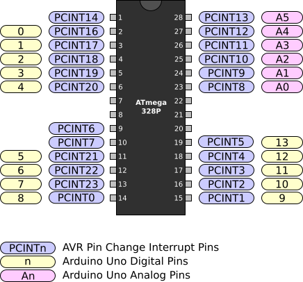
Figure 1. ATmega328P PDIP Pin Change Interrupt Pins
The pin change interrupt pins are divided into three separate groups. PCINT0 - PCINT7 trigger Pin Change Interrupt 0. PCINT8 - PCINT14 trigger Pin Change Interrupt 1. PCINT16 - PCINT23 trigger Pin Change Interrupt 2.
To enable a pin for a pin change interrupt, first set the appropriate bit in the Pin Change Mask Register. Next you will need to enable the appropriate Pin Change Interrupt in the Pin Change Interrupt Control Register. The following example shows enabling pin change interrupt on PCINT18.
1
2
3
4
5
// Enable pin change interrupt on the PCINT18 pin using Pin Change Mask Register 2 (PCMSK2)
PCMSK2 |= _BV(PCINT18);
// Enable pin change interrupt 2 using the Pin Change Interrrupt Control Register (PCICR)
PCICR |= _BV(PCIE2);
A full working example of using the pin change interrupt is listed below. This example configures PD2 as an input with a pull-up resistor and enables PCINT18 to trigger when the pin changes. If the pin is high, PB5 outputs a low value, which will turn the LED off. If the pin is low, PB5 outputs a high value, which will turn the LED on.
1
2
3
4
5
6
7
8
9
10
11
12
13
14
15
16
17
18
19
20
21
22
23
24
25
26
27
28
29
30
31
32
33
34
35
36
37
38
39
40
41
42
43
44
45
46
47
48
49
#include <avr/io.h>
#include <avr/interrupt.h>
ISR(PCINT2_vect)
{
// Read PD2 using the Port D Pin Input Register (PIND)
if (PIND & _BV(PIND2))
{
// PD2 is high, so button is released
// Set PB5 low using the Port B Data Register (PORTB)
PORTB &= ~_BV(PORTB5);
}
else
{
// PD2 is low, so button is pressed
// Set PB5 high using the Port B Data Register (PORTB)
PORTB |= _BV(PORTB5);
}
}
int main(void)
{
// Configure PD2 as an input using the Data Direction Register D (DDRD)
DDRD &= ~_BV(DDD2);
// Enable the pull-up resistor on PD2 using the Port D Data Register (PORTD)
PORTD |= _BV(PORTD2);
// Enable pin change interrupt on the PCINT18 pin using Pin Change Mask Register 2 (PCMSK2)
PCMSK2 |= _BV(PCINT18);
// Enable pin change interrupt 2 using the Pin Change Interrrupt Control Register (PCICR)
PCICR |= _BV(PCIE2);
// Configure PB5 as an output using the Port B Data Direction Register (DDRB)
DDRB |= _BV(DDB5);
// Enable interrupts
sei();
// Loop forever
while (1)
{
// Nothing to do here
// All work is done in the ISR
}
}
The circuit for this example should be wired according to Figure 1. If you run this example on an Arduino Uno, you will see the LED that is connected to Arduino pin 13 turning ON when the push button is pressed and turning OFF when the push button is released.
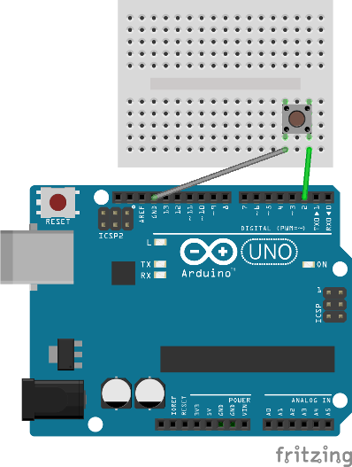
Figure 1. Input example wiring
Make sure to orient the push button correctly. If it is rotated the wrong way, the LED will always be on.